Modbus TCP client
Available from firmware 2024.6
Modbus is a long-living communication standard in industrial automation. It has been developed to communicate via TCP and meeting security needs.
There are different Modbus implementations available, e.g. as a function block (available in the PLCnext Store). But using a function block, its instantiation is necessary for each and every Modbus connection, and also for each and every function code (FC) call. Therefore, when working within a larger structure that gets confusing and exhausting for developers.
There are already some other custom implementations, some programmed in high-level languages, that are more convenient to use in development.
And from firmware release 2024.6 on, there is a Modbus TCP Client directly implemented into the Automation Runtime Platform (ARP) of PLCnext Technology. This Modbus TCP Client can be configured via the PLCnext Engineer programming software. The implementation depends on the libmodbus open source library, provided by libmodbus.org.
Note: So far, PLCnext Technology does not provide an accompanying Modbus TCP server solution.
How to configure a Modbus TCP communication
- Make sure the Modbus TCP Client service is activated on your controller (System services page in the Web‑based Management).
- Open the PLCnext Engineer software suite (v2024.6 or newer) and start a project from a template for your device.
- Import the PLCnext Engineer Modbus TCP Client library:
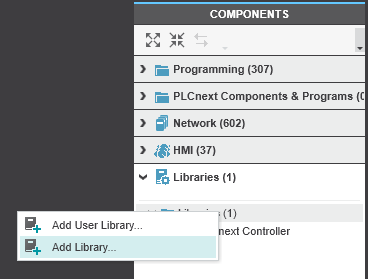
- In the COMPONENTS panel, right-click on the Libraries section.
- Right-click the Libraries folder and select Add Library from the context menu:
- From the PLCnext Engineer directory that opens in the Windows Explorer, pick the Modbus.pcwlx library.
↪ The Modbus library is copied into your PLCnext Engineer project.
↪ A Modbus node becomes visible in the Network section of the COMPONENTS panel:

- To assign the Modbus TCP Client feature to your device, unfold the Modbus → Devices folder stack down to the Modbus TCP Client items:

The number indicates how many communication lines to Modbus TCP servers can be set up; that depends on the PLCnext Control type running the Modbus TCP Client feature:PLCnext Control maximum Modbus servers AXC F 1152 8 AXC F 1252 8 AXC F 2152 16 AXC F 3152 16 RFC 4072S 16 RFC 4072R 16 BPC 9102S 16 VPLCNEXT CONTROL 1000 8 VPLCNEXT CONTROL 2000 16 VPLCNEXT CONTROL 3000 32 - Click and drag the appropriate item for your PLCnext Control from the right-side COMPONENT panel over to the left-side PLANT panel and drop it onto the controller.
↪ A Modbus TCP node becomes visible:

- Double-click the Modbus TCP node in the PLANT panel to open the Modbus Device List tab in the working area.
- Assign the IP addresses of the Modbus TCP gateways or servers you want to communicate with:

- To open the Modbus configuration, double-click the according Modbus TCP device in the PLANT view.
↪ The Settings page becomes visible:

- Check and change the default timing parameters for the server connection:
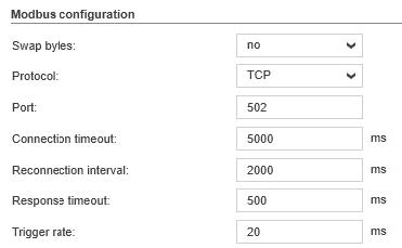
Swap bytes can be activated if necessary Protocol by now, only TCP is available Port default is 502Connection timeout specifies how long the client waits for a response in this cycle of establishing a connection before a new connection is possible Reconnection interval specifies how long to wait for a new attempt to establish a connection Response timeout specifies how quick the Modbus server should respond to the client's Modbus telegram; otherwise an error is issued to the diagnostic register Trigger rate Cycle time of the telegrams sent to the Modbus TCP server - Switch to the Registers tab to set up the Modbus function codes (FC) and data types for your application, e.g.:
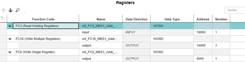
↪ The function codes are then connected to global variables which you can are also see listed at the bottom of the Data List tab as Process data items.
Once you have set up function codes in the above Registers tab, then you can work with these global variables in your automation programs.
Reference
![]() Find detailed information and instructions on Modbus TCP configuration by means of PLCnext Engineer in the PLCnext Engineer Online Help for the 2024.6 software release (or newer).
Find detailed information and instructions on Modbus TCP configuration by means of PLCnext Engineer in the PLCnext Engineer Online Help for the 2024.6 software release (or newer).
Supported function codes
These are the Modbus function codes (FC) that are supported by the PLCnext Technology Modbus TCP Client:
| FC | Description |
|---|---|
| 01 | Read Coils |
| 02 | Read Discrete Inputs |
| 03 | Read Holding Registers |
| 04 | Read Input Registers |
| 05 | Write Single Coil |
| 06 | Write Single Register |
| 15 | Write Multiple Coils |
| 16 | Write Multiple Registers |
| 23 | Read/Write Multiple Registers |
Diagnostic registers
For each configured Modbus server, PLCnext Engineer creates the defined IN and OUT ports. At runtime, the firmware puts values to the OUT ports and monitors the IN ports.
The diagnostics register is read out and displayed in the PLCnext Engineer diagnostic view:
| Process data item | Port type | Function | Data type |
|---|---|---|---|
IP_ADDRESS |
OUT | IP address of the server as a 32-bit value | Unsigned32 |
UNIT_ID |
OUT | Unit ID | Unsigned32 |
OFFLINE_CNT |
OUT | Counts the number of connection losses | Unsigned32 |
EXCEPTION_CNT |
OUT | Counts the number of exceptions received | Unsigned32 |
EXCEPTION_CODE |
OUT | A single exception code received | Unsigned32 |
EXCEPTION_FC |
OUT | Function code (FC) of the exception | Unsigned32 |
EXCEPTION_REG_ADDR |
OUT | Modbus register address of the exception | Unsigned32 |
AVG_NET_CYCLE_TIME |
OUT | Average update time (in ms) for updating the IO data per server | Unsigned32 |
MIN_NET_CYCLE_TIME |
OUT | Minimum update time (in ms) for updating the IO data per server | Unsigned32 |
MAX_NET_CYCLE_TIME |
OUT | Maximum update time (in ms) for updating the IO data per server | Unsigned32 |
ACTUAL_NET_CYCLE_TIME |
OUT | Update time (in ms) for updating the I/O data per server | Unsigned32 |
STATE |
OUT | Communication status: If the bit 0 value is 1 = TRUE, then a TCP communication is active.If the bit 1 value is 1 = TRUE, then a notice is present and the EXCEPTION_CODE register is set.Note: Phoenix Contact recommends to read Modbus process data only if the STATE variable has no exception (bit 1 not set) and the EXCEPTION_CODEis 0.(TCP communication is running and no exception is present).
|
|
ADDITIONAL_ERR |
OUT | Value range 0x1000 to 0x1fff: Error code 1001 means that the Modbus connection is not reachable.Value range 0x2000 to 0x2fff:Internal error - ask Phoenix Contact for support via the Forum |
|
CONTROL_DIAG_STATISTIC |
IN | If the bit0 value is set to 1 = TRUE, then all diagnostic data of the respective server connection will be reset (time measurement and error code).If the bit 31 value is set to 0 = FALSE (default), then the server connection will be activated if possible.If the bit 31 value is set to 1 = TRUE, then the server connection will be disabled. |
|
Known issue
Known for firmware 2024.6 on all supported PLCnext Control devices - fixed with firmware 2025.0:
Invalid and changing input data can occur in the event of a Modbus exception. This error will be fixed with a further firmware release. Meanwhile, as a workaround, process the read data only if the TCP communication is active and no exception is reported. That is true if the STATE variable has the value 16#0001.
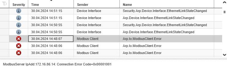
Notifications
PLCnext Engineer users will also find the familiar built-in notifications which can contain plain text, such as "connection lost", "wrong Modbus address", or timeout messages.