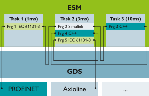
Global Data Space (GDS)
The GDS enables communication relationships and data exchange between tasks and programs that were created in different programming languages. The GDS also ensures that inconsistencies as shown in the following example are prevented:
While tasks are being processed and data is being exchanged directly between tasks, read and write access can overlap due to different cycles and intervals. In this example, task 1 – with medium priority – begins processing and, once completed, outputs a value.

That value is used by task 2 as an input value. Task 2 starts processing using this input value, and then processing is interrupted by another start of task 1. Task 1 has a higher priority and is processed again, while task 2 is paused. At the end of processing task 1, a new value is output that is again sent to task 2 as an input value. Once task 1 is finished, processing of task 2 is continued. However, because the input value has changed in the meantime, there is a data inconsistency which may lead to problems. The use of the GDS can prevent such inconsistencies.
Port-based communication
With the GDS, it is easy to establish communication relationships between different programs. This communication between the PLCnext Technology programs is implemented via ports. A port presents an endpoint of a component within a PLCnext Technology application. Via a port, data can be exchanged with other components (e.g., program instances and I/O systems). To enable this type of data exchange, the program variables to be exchanged or process data of the I/O components are defined as IN or OUT ports.
The data that is written from the tasks to the GDS is written via OUT ports. Tasks that receive input data read this data from the GDS via IN ports. Using the ports ensures data consistency and correctly functioning of the inter-task communication relationships at all times.

The IN and OUT ports are coupled via buffer mechanisms and synchronized during execution.
- Start of a task cycle (
OnTaskExecuting):
The IN ports are read from the GDS buffers by the program instances to be called in the task. - End of a task cycle (
OnTaskExecuted):
The OUT ports are written to the GDS buffers by the program instances to be called in the task.
The following figure shows the behavior of Task1 during port communication with Task1 buffer:

Data exchange for IN ports and OUT ports takes place at the beginning and at the end of each task execution. This only concerns data exchange of IN and OUT ports whose programs have been instantiated in different tasks. Ports within the same task are exchanged within the task. Furthermore, data exchange is only executed if the program instances are linked via IN and OUT ports. This ensures that the data is always stable and consistent during execution.
The following figure shows the behavior of Task1 and Task2 during Port communication with Task1 and Task2 buffers:

The following applies to the connection of IN and OUT ports:
- OUT ports can be shared within an application. An OUT port can be connected to several IN ports.
- An IN port can only be connected to one OUT port.
Further information on connecting ports is available in the PLCnext Engineer Online Help (search for Role mapping: Assigning PLCnext ports).
Fieldbus connection
Connection via IN and OUT ports
In addition to the communication between different tasks, process data from and to fieldbusses can also be exchanged via IN and OUT ports. Fieldbus systems also have buffers, although these are arranged logically within the fieldbus component itself. Values are written to and read from these buffers by the GDS. The fieldbus performs further handling.
This example shows the behavior of fieldbus communication via ports:

All components of a PLCnext Technology application that are part of the data exchange as well as I/O components must be connected via IN and OUT ports. At the beginning of a task, the task retrieves the data from the buffer. At the end of the task, the calculated values are actively rewritten to the buffer. Therefore, the buffer is the data exchange area between an IN port and an OUT port. The IN and OUT port connection between fieldbus components and tasks shows an analog behavior to the data exchange via ports between several tasks (see the Port-based communication section above).
By using the IN and OUT ports, the variable values are updated in the task context. The data is written to or read from the GDS buffer and is available to a task for the entire cycle. Using the IN and OUT ports secures task-internal data consistency. The fieldbus data is consistent as it comes from the same sampling cycles, and is also consistent within the task cycles. This also applies if programs are interrupted and a fieldbus is updated within this period of interruption. The variable value is buffered in the GDS and is available to the task for the period of time it requires to process all related programs, even with interruption.
When a fieldbus is connected to an ESM task, I/O data can be exchanged via the IN and OUT ports. For this, declare the variables in the data list of the PLCnext node of PLCnext Engineer as IN or OUT ports. The I/O data is updated in the update cycles of the ESM task.
Example port connection
A cyclic task has an update rate of 30 ms, for example. The user programs of the task consume the I/O data of the linked I/O variables. The I/O variables are updated at a cycle of 30 ms and are available to the programs. In this way, the programs in the task can also use the latest values. At the beginning of the task, the data is written from the fieldbus OUT port to the IN port of the task. At the end of the task, the output data is written to the IN port of the fieldbus via the OUT port of the task.

Connection via resource-global variables
Note:
To avoid inconsistent I/O data and the resulting errors, Phoenix Contact recommends to implement the fieldbus connection via the IN and OUT ports.
Resource-global variables as input:
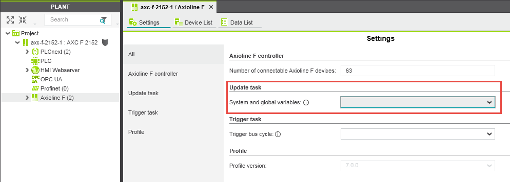
When creating your application, remember that there is no claim for data consistency when using resource-global variables. According to IEC 61131-3, resource-global variables can be used as an input in all Program Organization Units (POU) of the current resource. Several ESM tasks can access the fieldbus I/O data declared as resource-global variables. The update rate of the resource-global variables always depends on only one task. For the update behavior, an ESM task can be selected. You can make the setting in PLCnext Engineer:
- Open the respective node in the PLANT area for this.
- From the Update task drop-down list in the Settings editor, select the desired task.

Note: GLOBALS task update behavior
If no update task is selected that triggers the update cycle, the GLOBALS task is used (low priority and update rate of 50 ms). You can set one update task each for the groups fieldbusses, the ESM system variables and the system variables of the web server (PLCnext Engineer) HMIs.
Note: The priorities in the PLCnext firmware are set to update the I/O of the fieldbusses (Axioline, PROFINET, INTERBUS, EtherNet/IP™, etc.) with the highest priority. Then, ESM tasks are processed for which a priority has been configured. An exception is the IDLE task; it is processed with the lowest priority.
Up to firmware version 2020.9: The GLOBALS task is processed in the priority range higher than the IDLE task and lower than the other ESM tasks.
From firmware version 2021.0 LTS: The GLOBALS task is processed in the priority range lower than any other ESM task.
Other firmware tasks (e.g., OPC UA®, web server, communication with PLCnext Engineer) are processed with a priority lower than that of the IDLE task.
Note from firmware version 2025.0: The task GLOBALS has been managed by the ESM and was therefore executed only when the PLC was in RUN state. From firmware version 2025.0 this task is managed by the GDS. This means that the task is also executed regardless of the controller state, for example even if the controller is in STOP state. System variables in particular are updated in this state (for example PND_S1_RUN) and their values can be viewed via eHMI or OPC UA, for example.
Resource-global variables as output:
Usually, resource-global variables are only used once as an output to avoid unintentional overwriting of values.
Note: If you use resource-global variables several times as an output, the last value overwrites the previous values.
Example of fieldbus connection via resource-global variables
In the example in this figure, the update rate of the global variable depends on the cycle time of ESM task 1. The update time of 30 ms for the global variables therefore also applies to ESM task 2 and other tasks, if applicable. The cycle time of ESM task 2 is 20 ms. Still, it must process the cycle using the values synchronized by task 1. For task 2, this means that the data does not exactly correspond to the current process data image of the fieldbus components, but that data can be up to 30 ms old.

Interruption of tasks
If task 2 from the example in above figure has a higher priority than task 1, it might be the case that task 1 is interrupted by task 2 when updating fieldbus data. Then, task 2, with its higher priority, is processed. When task 2 is processed, there already is an updated data image from the fieldbus due to the update rate. The interrupted task 1 is now continued and accesses the fieldbus data that is still missing. However, this data is not consistent with the data retrieved before interruption.
Take this behavior into consideration when creating your application. Processing inconsistent data can result in errors in the process.
Comparison of connections via IN and OUT ports and resource-global variables
Connection via IN and OUT ports:
- Fieldbus data is consistent as it was retrieved and written to the buffer at the same time.
- Thanks to the GDS buffers, fieldbus data is consistent during task processing.
- The user is not responsible for data consistency as it is ensured via the GDS buffer storage units.
- Connecting IN and OUT ports of the task and fieldbus components is complex and less flexible than using resource-global variables.
Resource-global variables:
- At first sight, using resource-global variables seems to be quite easy.
- Update rates and interruptions of tasks due to priority can result in inconsistencies in the process data image.
- Inconsistent data can result in errors in the application.
- The user is responsible for data consistency, which is not ensured by the system.
See also